4.1 - Vapor-Compression Refrigeration Cycle
Module: Refrigeration Cycle Components Gauges and Pressure-Temperature Relationships
Course role: Introduces the four basic components of the vapor-compression refrigeration cycle, refrigerant-flow direction, heat absorption, heat rejection, and compressor work input
Learning Objectives
After completing this section, a student should be able to:
- Identify the compressor, condenser, metering device, and evaporator in a basic vapor-compression refrigeration system.
- Trace refrigerant flow through the four major components in the correct sequence.
- Explain the primary function of each major component.
- Identify where heat is absorbed, where heat is rejected, and where mechanical work enters the cycle.
- Explain why the compressor and metering device establish the pressure difference needed for refrigeration.
- Distinguish the purpose of refrigeration from the incorrect idea that a system “creates cold.”
Introduction
The vapor-compression refrigeration cycle is the basic operating cycle used in most conventional refrigerators, air conditioners, heat pumps, and mechanical refrigeration systems.
The cycle uses a circulating refrigerant to transfer heat from a lower-temperature region to a higher-temperature region.
A basic system contains four major components:
- Compressor
- Condenser
- Metering device
- Evaporator
The refrigerant continuously circulates through these components in a closed loop.
A useful starting sequence is:
Compressor
→ Condenser
→ Metering Device
→ Evaporator
→ Compressor
Each component performs a different function.
The basic heat-and-work picture is:
Cooled space / product
        │
        │ Heat absorbed
        ▼
     Evaporator
        │
        ▼
     Compressor ← Work input
        │
        ▼
     Condenser
        │
        │ Heat rejected
        ▼
  Outdoor air / water
The refrigeration system does not destroy heat and does not manufacture “cold.” It moves heat.
That idea is fundamental to understanding later EPA 608 topics such as:
- Refrigerant recovery.
- System pressures.
- Gauge connections.
- Pressure-temperature relationships.
- Superheat.
- Subcooling.
- Refrigerant charging.
- System diagnosis.
Key Concepts
1. The Four-Component Cycle
The vapor-compression cycle can be understood as four connected processes.
| Component | Primary Function | Main Energy Effect |
|---|---|---|
| Compressor | Compresses refrigerant vapor and circulates refrigerant | Work is added |
| Condenser | Rejects heat and condenses refrigerant vapor toward liquid | Heat is rejected |
| Metering device | Restricts and meters refrigerant flow while creating a large pressure drop | Pressure and saturation temperature decrease |
| Evaporator | Absorbs heat and boils refrigerant toward vapor | Heat is absorbed |
The four components must work together.
A compressor alone cannot provide refrigeration.
A condenser alone cannot provide refrigeration.
An evaporator can absorb heat only when the system maintains conditions that allow the refrigerant to evaporate at a sufficiently low temperature.
2. Refrigerant Flows in One Continuous Direction
In a basic operating cooling cycle, refrigerant flows:
Compressor discharge
→ Condenser
→ Metering device
→ Evaporator
→ Compressor suction
The cycle then repeats.
Another useful way to memorize the sequence is:
Compress
→ Condense
→ Meter
→ Evaporate
→ Repeat
The refrigerant does not normally reverse direction in a simple cooling-only circuit.
A heat pump may use a reversing valve to change which heat exchanger acts as the evaporator or condenser. That system arrangement is beyond the immediate scope of this section, but the basic vapor-compression processes remain the same.
The Compressor
1. Compressor Function
The compressor receives refrigerant vapor from the evaporator side of the system.
Its major functions are to:
- Draw low-pressure refrigerant vapor from the evaporator.
- Compress the vapor to a higher pressure.
- Raise the refrigerant vapor temperature as a result of compression.
- Move refrigerant through the system.
- Help maintain the pressure difference between the high side and low side.
In simplified form:
Low-pressure vapor
→ Compressor
→ High-pressure vapor
The detailed refrigerant state before and after each component is developed in Section 4.2 - Refrigerant State Through the Cycle.
2. Compressor Work Input
The compressor is the component that receives the major mechanical work input in the basic refrigeration cycle.
The compressor is usually driven by:
- An electric motor.
- An engine in some specialized systems.
- Another mechanical power source in some industrial applications.
The work input raises the refrigerant’s pressure and energy level so that the refrigerant can later reject heat at the condenser.
A refrigerator therefore requires energy to move heat from a colder region to a warmer region.
3. Why Compression Is Necessary
Heat naturally flows from a higher temperature to a lower temperature.
The refrigeration system must move heat in the opposite overall direction:
Lower-temperature space
→ Higher-temperature surroundings
To accomplish this, the cycle creates two different pressure and temperature regions.
The compressor raises refrigerant pressure on the discharge side.
At the higher pressure, the refrigerant can have a saturation temperature high enough to reject heat to:
- Outdoor air.
- Cooling water.
- Another heat sink.
The compressor therefore does more than simply “pump refrigerant.”
It helps establish the pressure condition required for condenser heat rejection.
4. The Compressor Is Designed to Compress Vapor
The compressor in a conventional vapor-compression system is intended to receive refrigerant primarily as vapor.
Liquid refrigerant entering a compressor can create serious mechanical problems because liquid is essentially incompressible compared with vapor.
Possible consequences of liquid entering the compressor include:
- Liquid slugging.
- Lubricant dilution.
- Bearing damage.
- Valve damage.
- Mechanical failure.
Later sections discuss accumulator function, superheat, charging, and liquid-refrigerant protection in more detail.
For this section, remember:
Compressor inlet → vapor is expected.
The Condenser
1. Condenser Function
The condenser is a heat exchanger located after the compressor in the normal refrigerant-flow direction.
Its primary purpose is to transfer heat from the refrigerant to another medium.
That other medium may be:
- Outdoor air.
- Water.
- Evaporatively cooled air/water.
- Another process fluid.
The basic process is:
High-pressure refrigerant vapor
→ rejects heat
→ condenses toward high-pressure liquid
2. Why the Refrigerant Can Reject Heat
Heat transfer requires a temperature difference.
The compressor raises the refrigerant pressure and temperature sufficiently so that, under normal operation, the refrigerant in the condenser is hotter than the cooling medium.
Therefore:
Hot refrigerant
→ heat transfer
→ cooler outdoor air or water
As heat is removed, refrigerant vapor condenses.
3. Condensation Is a Heat-Rejection Process
A very important exam relationship is:
Condensation rejects heat.
This is the opposite of evaporation.
During condensation:
Vapor
→ Liquid
and heat leaves the refrigerant.
In a real condenser, heat rejection can include:
- Cooling of superheated vapor.
- Latent heat released during condensation.
- Subcooling of liquid after condensation.
The detailed refrigerant-state changes are reserved for Section 4.2.
4. The Condenser Rejects More Heat Than the Evaporator Absorbs
The condenser must reject:
- Heat absorbed in the evaporator.
- Energy added to the refrigerant by compressor work.
For the simplified cycle energy balance:
where:
- = heat rejected at the condenser.
- = heat absorbed at the evaporator.
- = compressor work input.
This relationship explains why the condenser normally rejects more heat than the evaporator absorbs.
It also explains why the outdoor condenser of an operating air-conditioning system can reject both:
- Heat removed from the conditioned space.
- Heat equivalent to the compressor work input.
The Metering Device
1. Metering-Device Function
The metering device is located between the high-pressure condenser side and the low-pressure evaporator side.
Its two central functions are to:
- Meter refrigerant flow into the evaporator.
- Create a pressure drop between the high side and low side.
Common metering devices include:
- Thermostatic expansion valve (TXV).
- Electronic expansion valve (EEV).
- Capillary tube.
- Fixed orifice.
- Piston-type metering device.
The exact device varies with system design.
2. Pressure Drops Across the Metering Device
The refrigerant approaches the metering device at relatively high pressure.
As it passes through the restriction:
High pressure
→ Metering device
→ Low pressure
The reduced pressure produces a lower saturation temperature.
This allows the refrigerant entering the evaporator to boil at a temperature low enough to absorb heat from the space, product, air, water, or process being cooled.
3. The Metering Device Does Not “Make Cold”
A common oversimplification is:
“The expansion valve makes the refrigerant cold.”
A more accurate technician-level explanation is:
- The metering device creates a large pressure drop.
- The lower pressure corresponds to a lower saturation temperature.
- Some refrigerant flashes into vapor during the pressure-reduction process.
- The resulting low-pressure refrigerant can then absorb heat and boil in the evaporator.
The useful refrigeration effect occurs primarily because the evaporator receives refrigerant at a low enough pressure and saturation temperature to absorb heat from the load.
4. Compressor and Metering Device Work Together
The compressor and metering device establish the basic high-side/low-side pressure difference.
A simple conceptual picture is:
Compressor
→ raises refrigerant pressure

Metering device
→ drops refrigerant pressure
The condenser operates primarily on the high-pressure side.
The evaporator operates primarily on the low-pressure side.
High-side and low-side boundaries are developed in detail in Section 4.3 - High Side Low Side and Refrigerant Lines.
The Evaporator
1. Evaporator Function
The evaporator is the heat exchanger in which the refrigerant absorbs heat from the material or space being cooled.
The heat source can be:
- Indoor air.
- Refrigerator or freezer contents.
- Water.
- Glycol.
- Product in a refrigerated case.
- Process fluid.
The basic process is:
Low-pressure refrigerant
→ absorbs heat
→ evaporates toward vapor
2. Evaporation Is a Heat-Absorption Process
The most important relationship is:
Evaporation absorbs heat.
During evaporation:
Liquid
→ Vapor
and heat enters the refrigerant.
This is the useful cooling part of the cycle.
3. Why the Evaporator Must Be Cold Enough
Heat flows from warmer material toward colder material.
Therefore, to cool air or a product, the evaporator refrigerant must normally be at a sufficiently low temperature.
The pressure reduction produced by the metering device lowers the refrigerant saturation temperature.
This makes it possible for heat to flow:
Air / product / water
→ evaporator wall
→ refrigerant
4. The Evaporator Does Not “Add Cold” to the Space
A cooling system removes heat.
For example, in an air conditioner:
Warm indoor air
→ gives heat to evaporator
→ refrigerant carries heat away
The air leaving the evaporator is cooler because energy has been removed from it.
This distinction is important because many troubleshooting and exam questions are easier when the technician thinks in terms of heat movement rather than “cold movement.”
Refrigerant-Flow Direction Through the Cycle
1. Complete Basic Sequence
The complete simplified sequence is:
1. Compressor
   ↓
2. Condenser
   ↓
3. Metering Device
   ↓
4. Evaporator
   ↓
Back to Compressor
A technician should be able to start at any component and continue the sequence correctly.
Examples:
Starting at the evaporator:
Evaporator
→ Compressor
→ Condenser
→ Metering Device
→ Evaporator
Starting at the condenser:
Condenser
→ Metering Device
→ Evaporator
→ Compressor
→ Condenser
2. Four Component Transitions
| From | To | Main Reason |
|---|---|---|
| Evaporator | Compressor | Return low-pressure vapor for compression |
| Compressor | Condenser | Send high-pressure vapor to reject heat |
| Condenser | Metering device | Send high-pressure liquid toward pressure reduction |
| Metering device | Evaporator | Supply low-pressure refrigerant for heat absorption |
3. A Cycle Has No True Beginning or End
The refrigerant moves continuously while the system operates.
The cycle is often drawn beginning at the compressor for convenience, but no physical point is the permanent “start” of the cycle.
For exam preparation, what matters is knowing the correct sequence and function.
Heat and Work Around the Cycle
1. Three Energy Interactions
The simplest cycle has three major energy interactions:
Evaporator
→ heat enters refrigerant

Compressor
→ work enters refrigerant

Condenser
→ heat leaves refrigerant
The metering device provides pressure reduction and flow control but does not require the large mechanical work input associated with the compressor.
2. Heat Absorption
Heat absorbed in the evaporator is the useful refrigeration effect.
For a refrigerator, this can be heat removed from:
- Food.
- Cabinet air.
- Warm products placed inside.
- Heat leaking through the cabinet walls.
- Heat entering when the door opens.
For an air conditioner, this includes heat removed from indoor air.
3. Heat Rejection
Heat rejected in the condenser goes to the higher-temperature sink.
Examples include:
- Outdoor air at an air-cooled condenser.
- Condenser water in a water-cooled system.
The heat rejected contains both the evaporator load and the compressor work contribution.
4. Work Input
Mechanical or electrical energy supplied to the compressor allows the system to maintain a pressure difference and transfer heat from a low-temperature region to a higher-temperature region.
A refrigerator or air conditioner therefore cannot operate indefinitely without an energy input.
Basic Cycle Versus Actual Equipment
The four-component cycle is a simplified model.
Real systems can also contain:
- Receiver.
- Accumulator.
- Filter-drier.
- Sight glass.
- Solenoid valve.
- Check valve.
- Reversing valve.
- Oil separator.
- Service valves.
- Pressure controls.
- Sensors.
- Additional heat exchangers.
These components support:
- Refrigerant storage.
- Compressor protection.
- Moisture removal.
- Flow control.
- Oil management.
- Service.
- Safety.
- System control.
They do not change the four fundamental functions:
Compression
→ Heat rejection
→ Pressure reduction
→ Heat absorption
Receivers, accumulators, and filter-driers are developed in Section 4.4 - Receivers Accumulators and Filter-Driers.
Technical Details
1. The Idealized Cycle and the Real Cycle
In an ideal vapor-compression refrigeration cycle, the main processes are commonly represented as:
- Compression.
- Constant-pressure heat rejection.
- Throttling.
- Constant-pressure heat absorption.
Real systems differ from the idealized model because of:
- Compressor inefficiency.
- Pressure drop in piping and heat exchangers.
- Heat transfer to or from surrounding equipment.
- Superheat.
- Subcooling.
- Control behavior.
For EPA 608 preparation, the most important skill is not advanced thermodynamic cycle analysis.
The technician should first be able to identify:
- The component.
- The refrigerant-flow direction.
- Whether pressure is generally high or low.
- Whether heat is being absorbed or rejected.
- Whether work is being added.
2. Heat Exchangers Do Not Produce the Pressure Difference
The evaporator and condenser primarily transfer heat.
The basic pressure difference is maintained by:
- Compressor action.
- Flow restriction at the metering device.
This distinction helps prevent common troubleshooting errors.
3. Pressure Determines the Saturation-Temperature Level
The refrigeration cycle depends strongly on the refrigerant’s pressure-temperature relationship.
On the low side:
Lower pressure
→ lower saturation temperature
→ refrigerant can absorb heat in the evaporator
On the high side:
Higher pressure
→ higher saturation temperature
→ refrigerant can reject heat in the condenser
Detailed P-T chart use is covered in Section 4.7 - Pressure-Temperature Relationships.
4. Component Function Is More Important Than Component Appearance
A component should be identified by:
- Where it is located in the flow path.
- What it does to the refrigerant.
- Whether it receives or rejects heat.
- Whether it raises or lowers pressure.
Do not rely only on physical appearance.
For example, heat exchangers vary widely in construction:
- Tube-and-fin coil.
- Shell-and-tube.
- Plate heat exchanger.
- Microchannel coil.
- Tube-in-tube.
The condenser and evaporator can therefore look different from one system to another while performing the same basic thermodynamic functions.
Important Terms
Compressor
A compressor is a mechanical device that draws in refrigerant vapor, compresses it to a higher pressure, and drives refrigerant circulation through the vapor-compression system.
Condenser
A condenser is a heat exchanger in which refrigerant rejects heat to another medium and condenses toward the liquid state.
Evaporator
An evaporator is a heat exchanger in which low-pressure refrigerant absorbs heat from the cooled space, product, or process and evaporates toward vapor.
Heat Absorption
Heat absorption is the transfer of heat into the refrigerant. In the basic vapor-compression cycle, useful heat absorption occurs in the evaporator.
Heat Rejection
Heat rejection is the transfer of heat out of the refrigerant. In the basic vapor-compression cycle, the main heat-rejection process occurs in the condenser.
Metering Device
A metering device controls refrigerant flow into the evaporator and creates the pressure drop between the high-pressure and low-pressure sides of the system.
Refrigeration Cycle
A refrigeration cycle is a repeating thermodynamic process that transfers heat from a lower-temperature region to a higher-temperature region through refrigerant circulation and energy input.
Throttling
Throttling is the pressure-reduction process that occurs as refrigerant passes through a restriction such as a capillary tube, fixed orifice, or expansion valve.
Work Input
Work input is mechanical energy supplied to operate the compressor and raise the refrigerant from low pressure to high pressure.
Figures and Diagrams
Figure 4.1.1
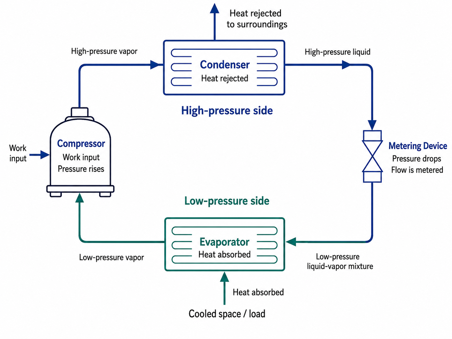
Figure 4.1.1 – Basic vapor-compression refrigeration cycle and energy-transfer directions.
AI-generated instructional figure: It may contain visual inaccuracies. Use the accompanying lesson text and cited authoritative sources to verify technical and regulatory details.
EPA 608 Exam Focus
What Students Must Remember
- The basic vapor-compression cycle contains:
- Compressor.
- Condenser.
- Metering device.
- Evaporator.
- Refrigerant-flow sequence:
Compressor
→ Condenser
→ Metering Device
→ Evaporator
→ Compressor
- Compressor
- Receives vapor.
- Raises pressure.
- Raises vapor temperature.
- Adds work to the cycle.
- Helps circulate refrigerant.
- Condenser
- Rejects heat.
- Changes refrigerant toward liquid.
- Metering device
- Meters refrigerant.
- Creates the pressure drop.
- Lowers saturation temperature by lowering pressure.
- Evaporator
- Absorbs heat.
- Changes refrigerant toward vapor.
- Evaporation absorbs heat.
- Condensation rejects heat.
- The cooling system moves heat; it does not create cold.
- The compressor and metering device establish the pressure difference that allows the evaporator and condenser to operate at different saturation temperatures.
- The compressor should normally receive vapor, not uncontrolled liquid.
- The condenser rejects the evaporator load plus the compressor-work contribution.
Typical Exam Question Patterns
Students may be asked to:
- Put the four major components in correct refrigerant-flow order.
- Identify which component increases refrigerant pressure.
- Identify which component causes the major pressure drop.
- Identify where refrigerant absorbs heat.
- Identify where refrigerant rejects heat.
- Identify where mechanical work enters the cycle.
- Determine which component should receive refrigerant vapor.
- Distinguish evaporation from condensation.
- Explain why the evaporator can absorb heat from the cooled space.
- Identify the basic high-pressure and low-pressure portions of the cycle.
High-Priority Comparison Table
| Exam Clue | Correct Component / Concept |
|---|---|
| Raises refrigerant pressure | Compressor |
| Mechanical work input | Compressor |
| Rejects heat | Condenser |
| Condenses refrigerant | Condenser |
| Meters refrigerant flow | Metering device |
| Major pressure drop | Metering device |
| Absorbs heat | Evaporator |
| Boils refrigerant | Evaporator |
| Low-pressure vapor returns here | Compressor |
| High-pressure liquid flows here next | Metering device |
Common Mistakes and Confusing Points
Mistake 1: Reversing the Refrigerant-Flow Sequence
Correct sequence:
Compressor
→ Condenser
→ Metering Device
→ Evaporator
→ Compressor
Not:
Compressor
→ Evaporator
→ Metering Device
→ Condenser
Mistake 2: Saying the Evaporator Rejects Heat
The evaporator absorbs heat.
The condenser rejects heat.
Mistake 3: Saying the Condenser Creates High Pressure
The compressor produces the pressure rise.
The condenser is the main high-side heat-rejection heat exchanger.
Mistake 4: Saying the Metering Device Compresses Refrigerant
The metering device does the opposite.
It creates a pressure drop.
Mistake 5: Saying the Metering Device Creates Cooling by Removing Heat
The metering device primarily reduces pressure and meters flow.
The useful heat-removal process occurs in the evaporator.
Mistake 6: Thinking Refrigeration Means Adding Cold
Cooling occurs because heat is removed from the cooled region.
Mistake 7: Assuming the Condenser Rejects Only the Heat Absorbed in the Evaporator
The condenser also rejects the energy associated with compressor work.
Mistake 8: Thinking Liquid Refrigerant Should Normally Enter the Compressor
A conventional compressor is intended to compress vapor.
Uncontrolled liquid entry can cause compressor damage.
Mistake 9: Confusing a Component’s Physical Size With Its Function
A condenser and evaporator can have many different physical forms.
Identify them by:
- Refrigerant-flow location.
- Heat-transfer direction.
- Pressure side.
- Function.
Mistake 10: Treating the Four-Component Diagram as Every Component in a Real System
Real equipment can include many additional devices.
The four-component diagram represents the fundamental refrigeration cycle.
Concept-Check Questions
Question 1
Which sequence correctly follows refrigerant flow through a basic vapor-compression refrigeration cycle starting at the compressor?
A. Compressor → Evaporator → Metering Device → Condenser → Compressor
B. Compressor → Condenser → Metering Device → Evaporator → Compressor
C. Compressor → Metering Device → Condenser → Evaporator → Compressor
D. Compressor → Condenser → Evaporator → Metering Device → Compressor
Question 2
What is the primary function of the compressor in the basic refrigeration cycle?
A. Raise the pressure of refrigerant vapor and provide the major work input to the cycle
B. Reduce refrigerant pressure before the evaporator
C. Reject heat from refrigerant to outdoor air or water
D. Absorb heat from the cooled space
Question 3
What is the primary heat-transfer function of the condenser?
A. Absorb heat from the conditioned space
B. Reduce refrigerant pressure
C. Add mechanical work to the refrigerant
D. Reject heat from the refrigerant to a cooler external medium
Question 4
Which component creates the major pressure drop between the condenser side and evaporator side?
A. Compressor
B. Condenser
C. Metering device
D. Evaporator
Question 5
What is the primary heat-transfer function of the evaporator?
A. Reject heat to the outdoor environment
B. Absorb heat from the space, product, or process being cooled
C. Raise refrigerant pressure
D. Store high-pressure liquid refrigerant
Question 6
For the simplified vapor-compression cycle, which relationship best represents the energy rejected at the condenser?
A. Condenser heat rejection equals evaporator heat absorption plus compressor work input.
B. Condenser heat rejection equals only compressor work input.
C. Condenser heat rejection is always less than evaporator heat absorption.
D. Condenser heat rejection is zero whenever the refrigerant condenses.
Question 7
Which refrigerant condition should normally enter a conventional vapor-compression compressor?
A. High-pressure liquid
B. Low-pressure liquid only
C. High-pressure liquid-vapor mixture
D. Low-pressure vapor
Question 8
Which statement best explains what a refrigeration system does?
A. It manufactures cold energy in the evaporator.
B. It destroys heat in the metering device.
C. It uses work input to move heat from a lower-temperature region to a higher-temperature region.
D. It converts all absorbed heat into mechanical work.
Answers and detailed explanations will be provided in
4.11 - Answers and Explanations.md.
Section Summary
The vapor-compression refrigeration cycle uses four fundamental components:
Compressor
→ Condenser
→ Metering Device
→ Evaporator
→ Compressor
The compressor:
- Receives low-pressure vapor.
- Raises refrigerant pressure.
- Adds work to the cycle.
- Drives refrigerant circulation.
The condenser:
- Rejects heat.
- Changes refrigerant toward the liquid state.
The metering device:
- Controls refrigerant flow.
- Creates the large pressure drop between the high and low sides.
- Lowers the saturation-temperature level for the evaporator.
The evaporator:
- Absorbs heat.
- Changes refrigerant toward the vapor state.
The three main energy interactions are:
Evaporator → heat absorbed
Compressor → work input
Condenser → heat rejected
For the simplified cycle:
The cycle therefore does not create cold. It uses energy to transfer heat from a lower-temperature region to a higher-temperature region.
The next section follows the refrigerant state around each component in greater detail.
See Section 4.2 - Refrigerant State Through the Cycle.
References
Project Source
- Current EPA Section 608 teaching-material project outline, Module 4 — Refrigeration Cycle Components Gauges and Pressure-Temperature Relationships, Section 4.1. Required scope: compressor, condenser, metering device, evaporator, refrigerant-flow direction, heat absorption, heat rejection, work input, and Figure 4.1.1.
EPA 608 Teaching Reference
- International Training Institute for the Sheet Metal and Air Conditioning Industry, EPA Section 608 Study Guide, Core refrigeration section, vapor-compression refrigeration cycle. The guide describes high-pressure liquid passing through the metering device, pressure and saturation-temperature reduction, evaporator heat absorption and boiling, low-pressure vapor entering the compressor, compression to high-temperature/high-pressure vapor, condenser heat rejection, condensation to high-pressure liquid, and repetition of the cycle.
HVAC Technical References
-
Rex Miller and Mark R. Miller, HVAC Licensing Study Guide, 3rd ed., refrigeration-system service discussion. The text describes refrigerant evaporation in the evaporator, vapor flow through the suction line to the compressor, compression that raises vapor pressure and temperature, condenser heat rejection and condensation, and metering through a capillary tube.
-
Edward G. Pita, Air Conditioning Principles and Systems: An Energy Approach, 4th ed., refrigeration and phase-change fundamentals used as the technical foundation for evaporation, condensation, heat absorption, and heat rejection.
-
Justin Kauwale, Mechanical PE: HVAC & Refrigeration Textbook, 2025 ed., vapor-compression refrigeration cycle discussion. The text treats the evaporator and condenser as heat exchangers, describes compressor pressure/temperature increase, condenser heat rejection and phase change, and expansion-device pressure reduction and flash gas.
-
Applied Thermodynamics, Chapter 11 — Refrigeration Cycles, instructional material on the ideal and actual vapor-compression refrigeration cycles. The material identifies compression, condenser heat rejection, throttling, and evaporator heat absorption as the four fundamental cycle processes.